|
msbGrid
1.0
|


|
|
msbGrid
1.0
|
|
We demonstrate here how to use msbGrid to create a 3-blocks quadrilateral hybrid (structured-unstructured) grid. This same grid is used in the Two phases fluid flow in fractured porous media section.
| Parameter | description |
|---|---|
| xMin | bounding box minimum x value (yMin = xMin) |
| xMax | bounding box maximum x value (yMax = xMax) |
| bnCx | block number in the x direction |
| bnCy | block number in the y direction |
| dr | blocks elements (square in 2D) side length |
| rafC | rafinement coefficient in the inter blocks area |
| bCId | randomly generated block centers identifier |
| bAId | randomly generated block angles identifier |
| bCPC | block centers perturbation coefficient, the perturbation magnitude = bCPC * dr |
| d2bC | distance to the boundary coefficien, the distance to the boundary = d2bC * dr |
| intbC | inter-blocks coefficient, the inter-blocks distance = intbC * dr |
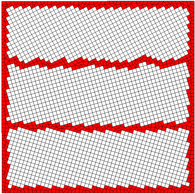
/// file: msbGrid_ctest_1.geo

Include "blPtExtBound_.geo";
Include "vBlPtI_.geo";
Include "vEdExtBound_.geo";
Include "vBlEd_.geo";
Include "vBlQd_.geo";
Include "blockBoundary_.geo";

Mesh.RecombineAll = 1;
/// file: blPtExtBound_.geo

//////////////////////////////
// external boundary points //
//////////////////////////////
Point(1) = {0.000000, 0.000000, 0.000000, 0.020000};
Point(2) = {0.000000, 1.000000, 0.000000, 0.020000};
Point(3) = {1.000000, 1.000000, 0.000000, 0.020000};
Point(4) = {1.000000, 0.000000, 0.000000, 0.020000};
/// file: vBlPtI_.geo

/// Block 1
Point(5) = {0.487513, 0.160027, 0.000000, 1.000000};
Point(6) = {0.506639, 0.154180, 0.000000, 1.000000};
...

/// Block 2
Point(767) = {0.487631, 0.506856, 0.000000, 1.000000};
Point(768) = {0.493144, 0.487631, 0.000000, 1.000000};
...

/// Block 3
Point(1542) = {0.486550, 0.837703, 0.000000, 1.000000};
Point(1543) = {0.495630, 0.819883, 0.000000, 1.000000};
...
Point(2256) = {0.020511, 0.959389, 0.000000, 1.000000};
/// file: vEdExtBound_.geo

//////////////////////////////
// external boundary lines  //
//////////////////////////////
Line(1) = {1, 2};
Line(2) = {2, 3};
Line(3) = {3, 4};
Line(4) = {4, 1};
/// file: vBlEd_.geo

/// Block 1
Line(5) = {5, 6};
Line(6) = {5, 7};
...

/// Block 2
Line(1450) = {767, 768};
Line(1451) = {767, 769};
...

/// Block 3
Line(2921) = {1542, 1543};
Line(2922) = {1542, 1544};
...
Line(4269) = {2254, 2255};
/// file: vBlQd_.geo

/// Block 1
Line Loop(1) = {+5, +7, -8, -6};
Plane Surface(1) = {1};
Transfinite Line{5, 7, 8, 6} = 2 Using Progression 1;
Transfinite Surface{1} = {5, 6, 8, 7};
...

/// Block 2
Line Loop(685) = {+1450, +1452, -1453, -1451};
Plane Surface(685) = {685};
Transfinite Line{1450, 1452, 1453, 1451} = 2 Using Progression 1;
Transfinite Surface{685} = {767, 768, 770, 769};
...

/// Block 3
Line Loop(1382) = {+2921, +2923, -2924, -2922};
Plane Surface(1382) = {1382};
Transfinite Line{2921, 2923, 2924, 2922} = 2 Using Progression 1;
Transfinite Surface{1382} = {1542, 1543, 1545, 1544};
...
Line Loop(2016) = {+4256, +4268, -4269, -4262};
Plane Surface(2016) = {2016};
Transfinite Line{4256, 4268, 4269, 4262} = 2 Using Progression 1;
Transfinite Surface{2016} = {2233, 2234, 2255, 2254};

Physical Surface(2017) = {1:2016};
Color White {Surface {1:2016};}
/// file: blockBoundary_.geo

///////////////////////
// Block line Loops  //
///////////////////////

/// Boundary of Block 1, Line Loop 2017
Line Loop(2017) = {+237, -313, +314, +312, -310, +308, -481,..., -318, +319, +238};

/// Boundary of Block 2, Line Loop 2018
Line Loop(2018) = {+1706, -1792, -1794, -1798, -1802, -1894, -1895,..., -1881, +1782, -1787};

/// Boundary of Block 3, Line Loop 2019
Line Loop(2019) = {+3169, -3255, -3256, +3177, -3261, -3263, -3337,..., +3243, -3246, +3247};

//////////////////////////////////
// external boundary line Loop  //
//////////////////////////////////

/// Line Loop 2020
Line Loop(2020) = {+1, +4, +3, +2};

/////////////////////////////////
// inter-blocks plane surface  //
/////////////////////////////////

/// Plan Surface 2018
Plane Surface(2018) = {2017,2018,2019,2020};
Physical Surface(2018) = {2018};

Color Red {Surface {2018};}
 1.8.3.1